
4130 Chassis Tubing
A tube chassis is strong because of its geometry as much as its material. 4130 lets each member be lighter, but the layout decides whether the frame is stiff.
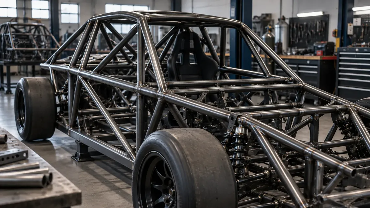
Spaceframe vs. Ladder Frame
Two primary chassis architectures use 4130 tube:
1. Spaceframe: A three-dimensional triangulated structure of tubes where loads are primarily axial (tension and compression). The triangulated geometry enables the highest efficiency from the tube material. Formula cars, sports racers, and many kit cars use spaceframe construction.
2. Ladder frame / tube frame: Two main longitudinal rails connected by cross-members. Simpler to fabricate but less structurally efficient per unit weight than a true spaceframe. Used in dragsters, truck chassis, and off-road vehicles.
Both architectures benefit from 4130's higher yield strength compared with mild steel DOM tubing.
Chassis Tube Selection
Chassis tube sizing is determined by engineering analysis of the loads in each member. Primary tubes (main frame rails, roll structure) typically use larger OD and heavier walls; secondary braces use smaller OD and lighter walls to save weight. The specific dimensions depend on the vehicle type, design load case, and designer's analysis.
| Chassis Application | Typical OD Range | Typical Wall Range |
|---|---|---|
| Primary frame rails (light car) | 1.250"–1.750" | 0.083"–0.120" |
| Secondary bracing | 0.750"–1.250" | 0.049"–0.083" |
| Roll hoop (light car) | 1.500"–1.750" | 0.083"–0.120" |
| Note | All values are general guidance — structural analysis required |
Triangulation and Nodes
A rectangle of tubes can fold into a parallelogram; a triangle cannot change shape without stretching or compressing a member. A well-designed spaceframe is therefore built from triangles, so that tubes are loaded along their length, where they are strongest, and not in bending.
The points where tubes meet are called nodes. Loads from suspension, engine and seat mounts should enter the frame at nodes. A bracket welded to the middle of an unsupported tube puts that tube in bending and invites cracking. Where several tubes meet, plan the order of fitting and welding so each joint is accessible and the tubes meet on their centrelines.
These principles explain why chassis use several tube sizes: larger tubes for long compression members that could buckle, smaller ones for short ties. Work out the members first, then the sizes. See 4130 tubing for racing chassis and the size chart.
Frequently Asked Questions
Does a 4130 tube chassis need to be heat treated after welding?
For most motorsport tube chassis built from as-drawn CDS 4130, post-weld normalising is not standard practice. The structural properties are typically calculated on the basis of the normalised condition yield strength, which is conservative for as-drawn material. Post-weld normalising is recommended for aircraft structures and high-stress welded assemblies.
Why are tube chassis triangulated?
A triangle holds its shape under load, so members carry load along their length instead of in bending.
What is a node in a tube frame?
A point where tube centrelines meet. Loads should be fed into the frame at nodes.
Source 4130 Chassis Tubing
Provide your chassis tube material list with OD and wall sizes, total footage per size, and MTC requirement.
- List of required OD & Wall sizes
- Footage per size
- Condition (as-drawn or normalized)
- MTC
- Delivery