
4130 Tubing for Racing Chassis
A racing chassis has to be straight as well as strong. Suspension pick-up points must sit exactly where the design puts them, and welding a tube frame tends to pull it out of shape.
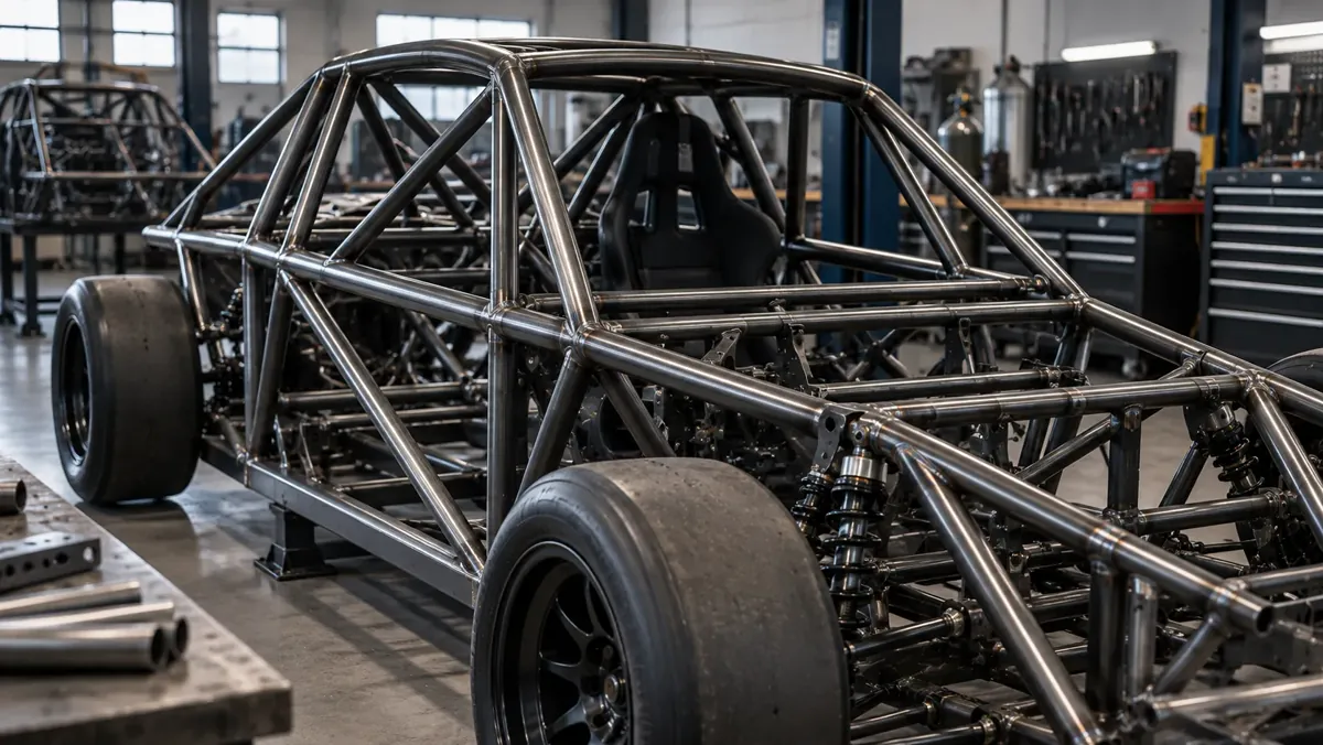
Spaceframe Engineering Principles
In a triangulated spaceframe:
- Members in compression must resist column buckling — the maximum tube length and minimum wall thickness are critical parameters
- Members in tension carry load up to the material's yield strength multiplied by the cross-sectional area
- Joints must be designed to efficiently transfer loads between members — typically by fishmouth notching and TIG welding at nodes
Proper spaceframe design requires engineering analysis of the load cases — braking, cornering, bump — not simply a copy of another design.
Tube Selection for Chassis Members
Chassis tube selection is a structural engineering calculation, not a catalogue selection. However, the following general guidance applies:
For compression members, the critical factor is the slenderness ratio (L/r, where L is tube length and r is radius of gyration). Shorter members with larger OD have better compressive efficiency. For tension members, wall thickness directly governs load capacity.
For typical formula racing chassis, main frame members use ODs in the 1.0"–1.5" range with walls of 0.049"–0.083". These values are general guidance — a structural engineer or experienced chassis designer must size members for the specific application.
| Member Type | Governing Failure Mode | Primary Sizing Factor |
|---|---|---|
| Compression diagonal | Column buckling | Slenderness ratio (L/r) |
| Tension diagonal | Yield / fracture | Cross-sectional area |
| Main rail | Bending + compression | Section modulus + wall area |
| Node area tubes | Shear / joint strength | Wall thickness + joint design |
| Note | All sizing requires structural analysis by qualified engineer |
Jigging and Build Sequence
Build on a flat, rigid table or a purpose-made jig that fixes the critical points: suspension mounts, engine mounts and the main bulkheads. Locate those points first and fit the tubes to them, not the other way round.
Every weld shrinks as it cools and pulls the structure toward it. To control that:
- Tack the whole frame together before fully welding any joint.
- Weld in a balanced sequence, alternating sides and ends.
- Weld joints in short sections around the tube instead of in one pass.
- Leave the frame in the jig until it has cooled.
- Check key dimensions after welding and before adding brackets.
Thin-wall 4130 moves more than heavy tube, so the lighter the chassis the more care the sequence needs. Order tube from consistent material and keep off-cuts for test joints. Design principles are outlined under 4130 chassis tubing; full-car material planning under 4130 tubing for race cars.
Frequently Asked Questions
Can I simply copy another car's chassis tube sizes?
Copying tube sizes without engineering analysis is not safe practice for a safety-critical structure. The loads depend on the specific vehicle's weight, power, and intended use. Use published designs only if they are engineered for your specific application, and verify that your build matches the design exactly.
Why does a tube chassis distort during welding?
Weld metal shrinks as it cools and pulls the joint. Balanced sequencing and a rigid jig limit the movement.
Should I fully weld each joint as I go?
No. Tack the complete frame first, then weld in a balanced sequence.
Source 4130 Chassis Tubing
Provide your chassis tube BOM — all OD/wall sizes and footage. Consolidated orders receive consistent MTC documentation.
- OD & Wall per member type
- Footage per size
- Standard: ASTM A519 CDS
- MTC 3.1 required
- Delivery